WB9UWA
Click to see Jim WB9UWA’s homemade XPOL array photos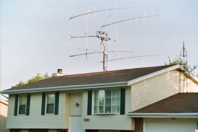
WB9UWA array detailed photos
Here are more photos of Jim's XPOL array for 144MHz.
Click on any photo for a closer look
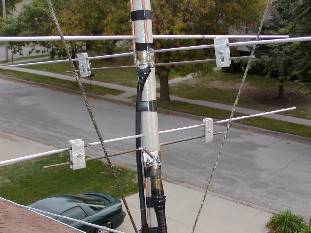
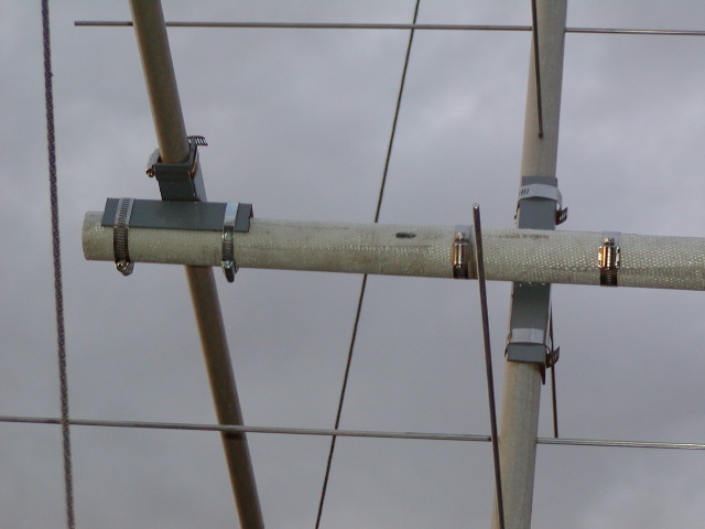
The vertical driven element is feed direct with LMR400uf. The shield of the LMR400uf and the shield of the RG142 balun is soldered to a brass sheet formed to the fiberglass boom. There is no connection between the brass sheet and the aluminum driven element. The baluns are routed to minimize H/V coupling.
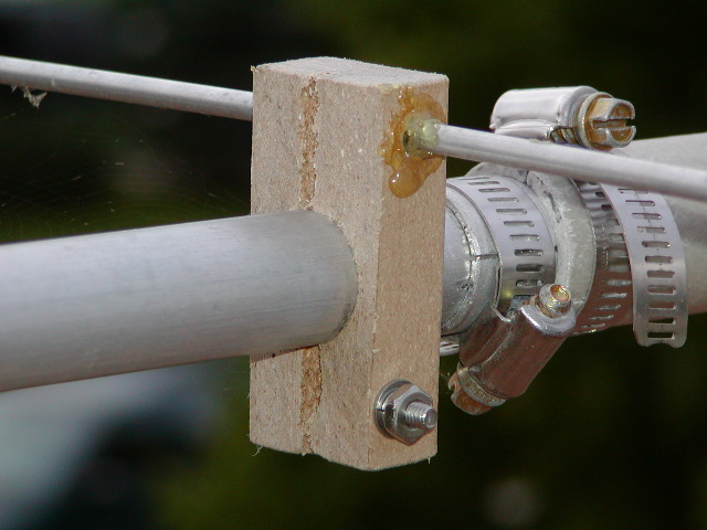
The front part of the boom is aluminium. The rear part of the boom is fiberglass. The element insulators on the aluminium part of the boom is made of a material that consist of plastic and wood particles, said to be weather proof. The material is called Ultra deck.
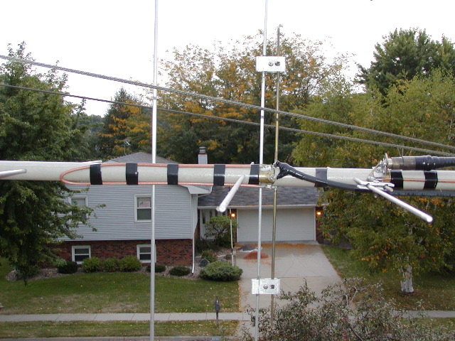
This view shows a good perspective of the geometry used to minimize H/V coupling between driven elements and feedlines.
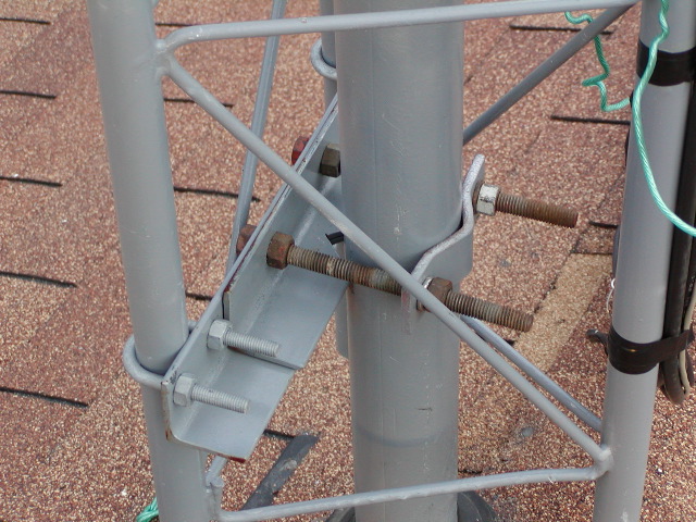
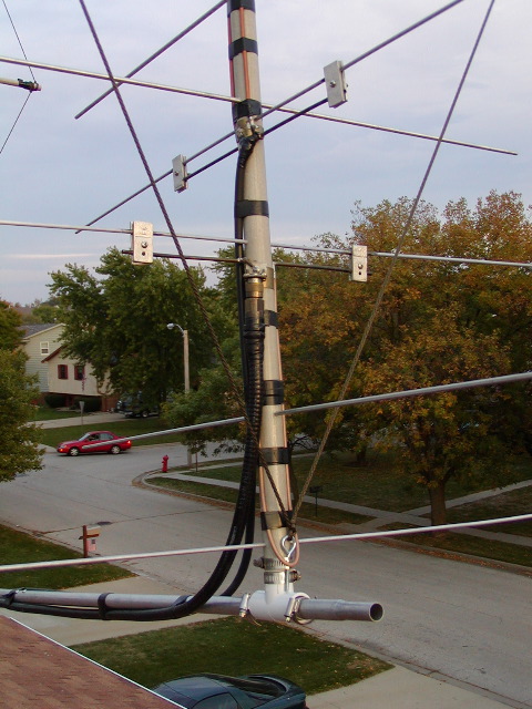
The weather boot keeps water out of the attic. The support pipe is 2 7/8" OD and 2" ID. One pipe was slid inside another to get this wall thickness. A heavy clamp holds the tower to the pipe. This is a view of the lower clamp.
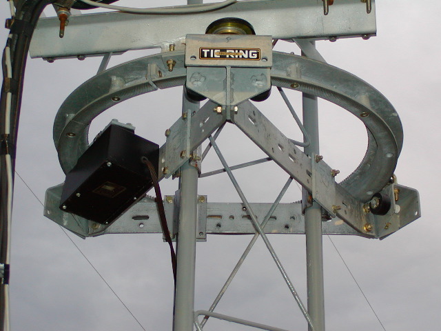
The Tick Ring rotor is heavy duty. It rotates around the 10 foot section of Rohn 25g tower. It uses a DC motor and runs on 24VDC. This makes it handy to rotate the array from the roof top location using a pair of 12 volt batteries in series. The rotor was installed at 6.5 feet above the roof initially. When the entire array was built using nothing more than step ladders, it was moved to its final height 8.5 feet above the roof using a low cost 2000 lb cable puller.
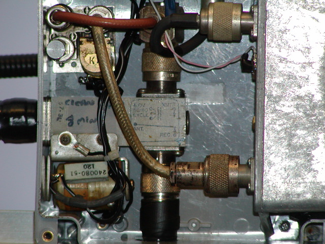
Inside the pre-amp box, a common relay switches the vertical antenna between TX and RX. The normal power off resting state is TX. The RX line feeds a low power 24 volt BNC relay to increase isolation and terminate the pre-amp in a 50 ohm load during TX, non-use, or for noise test. The actual pre-amp is a common design using surplus GaAsFET devices taken from old 4 GigiHerz LNAs. It is believed to be similar to the common MGF1302.
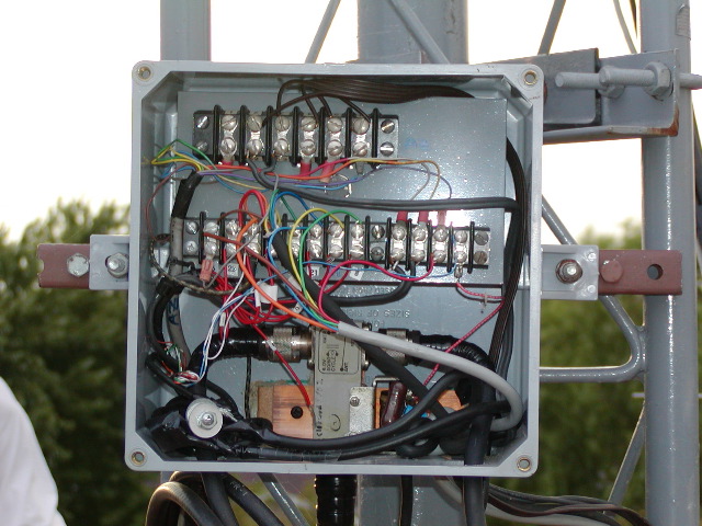
Inside the tower box, all the rotors are connected to the main multiconductor cable leading to the shack. Common terminal strips make the connections. The coaxial relay selects between the Vertical and Horizontal transmit antenna. Water is allowed to drain from the bottom of the otherwise waterproof box. DC is fed from this box up RG59u coax with BNC connectors to the pre-amp boxes.
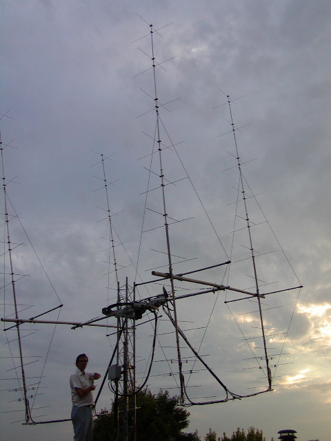
The designer/builder of the 4 X UWA12 Xpol array can be seen here standing next to his creation.
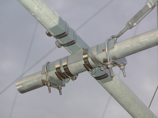
Angle iron, hose clamps and U bolts hold the vertical risers to the horizontal section of the H frame. A U bolt holds the end of the turnbuckle that is connected to a line that holds the horizontal section of the H frame horizontal at mid elevations.
Angle iron and hose clamps hold the yagi booms to the fiberglass risers. A fiberglass 5' 7" horizontal section of fiberglass tubing is held 1 foot above the boom in the same manner. This fiberglass tubing anchors the dacron lines for boom guying.
Aluminium tent poles are used behind the vertical reflectors to hold the feedlines and help stablize the array. PVC T connectors and hose clamps hold the tent poles to the back end of the yagis. An eye bolt is held by a hose clamp to provide an end anchor for the dacron boom support lines.