Elevation system for EME yagi arrays
I have included some Photos of my 144MHz Antenna system's elevation drive - I hope that you may find some of it useful. - GM4JJJ, Oct 96.
For elevating my antennas I have used a satellite TV Actuator (Jacking Screw) which has an 18" throw. They are not as expensive as a KR500 elevation rotator and are indestructible as far as I can see. They give positive braking and have minimal backlash.
Generally these actuators need 36V DC to drive them. (Reverse the supply polarity to reverse the direction of the arm).
Because they use DC motors, there is a little brush noise when moving them, but if you move them on TX cycles its not a problem.
I have used a Satellite TV Positioner unit to drive my actuator. That's a PSU, digital readout and memory box which is ideal for storing the elevation settings. The screw jack actuator has its own reed relay pulse system built in that is capable of very high accuracy once you calibrate it.
You have to calibrate it because the angle of elevation is not directly proportional to the extension of the arm. I finally calibrated mine with a protractor and a pair of binoculars! I get a full 0 to 90 degrees elevation.
Your actuator should have safety electrical limit switches built in to it that cut the supply when it gets near to it's end of travel. These are usually adjustable. They are built into the motor assembly on a cam and are microswitches.
In my case I also have electronic limits set by the positioner unit . The positioner knows not to go beyond a certain programmed pulse count.
You want to adjust the limit switches so that the actuator arm stops before it breaks something in your system. These actuators are really powerful and can do a bit of damage if you let them.
Note:- If you are testing your actuator arm in the shack before installation them it is important to hold the end of the arm so that it cannot spin, if you don't then the whole thing can unscrew itself!
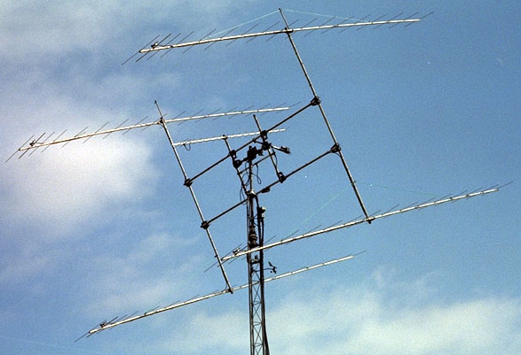
GM4JJJ Array
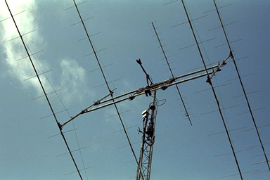
In the photo below you can see how the array is mounted nearer to the top of the H frame to make it bottom heavy. The elevation screw jack pushes against the weight of the array.
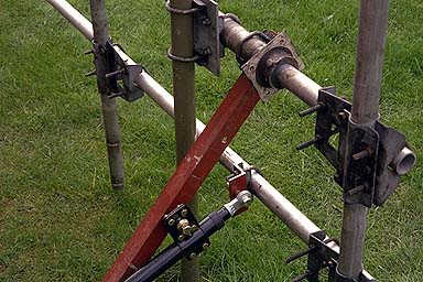
Elevation Drive details
The Prototype mock-up at ground level.
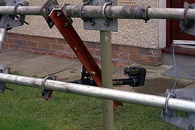
The red angle iron is fixed to the pipe with a U bolt.(It can't rotate). That pipe you see is a piece of 2" Pipe with a 1.5" Pipe throught the middle of it; this forms the elevation axle. The angle iron is only to hold the actuator fixed relative to the ground.
The bracket which hold the actuator to the angle iron is a pivot point and is normally supplied with the actuator and allows it to rotate freely. (Its a sort of a ball and socket arrangement). I found that I had to make a small mock up to test my ideas before I built the final system and I recommend that is what you should do. Most actuators have an adjustable bracket on them that slides up and down the the length of the fixed part of the actuator so that you can set them up for just about any situation.
18" Satellite TV Actuator Arm
Another view