Modifications to the W1SL 144MHz Power Amplifier
By David Anderson GM4JJJ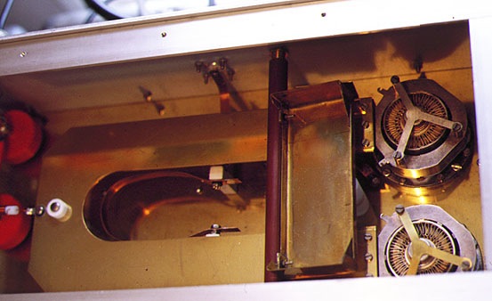
There follows a few notes showing the modifications I made to the Classic W1SL 144MHz Power Amplifier design. For important background and other details please read the References.
Download the original article in Adobe Acrobat PDF format (470K)
Photos of the PSU and the GM4JJJ W1SL amplifier.
In place of the expensive Eimac SK600 bases you can use the surplus "NATO UHF" Bases (the ones with the Y shaped clamp on the top) at 144MHz, though you will have to make some adjustments to the dimensions of the anode line. I measured the value of the screen bypass capacitor in the bases at 3.4nF. There is a variable capacitor fitted to the grid spigot which can be removed to reduce the height as it is not required. Also remove the white screen wire from the screen pin allowing the screen to be fed directly from the base in the grid compartment in the usual way.
These bases were available as surplus in the UK from :
Sinequanon (www.sinequanon.co.uk)
PO BOX 262
LoughBorough
LE11 1ZJ
UK
Tel:+44 (0)1509 238088
The Grid circuit is unchanged from the original article. Neutralising tabs are also as in original article.
See the following drawings for details of modified anode circuit etc. This was necessary because the valve bases are a larger diameter and need to be spaced further apart, hence the length of the line has to be shortened. The other nice thing is that the lines are straight for the full length, not needing to be bent up. Valve changes are very easy with these valve bases, no need to unfasten the anode line clamps! Bases are really cheap, I paid £8 for a pair in about 1983. Price in March 1999 was £18 for 2 bases, still quite reasonable.
In class AB1 the amplifier needs less than 1 watt of drive for 600 watts PEP output.
For EME use I can reduce the bias to allow class AB2 operation and with 5 watts drive get 1 KW out on CW. Get a transformer that will give about 1600 volts AC at 800mA for the EHT. You need +350V stab for the screens for SSB. (+300V for CW class AB2).
Transformers - I have found a very helpful firm that can supply custom wound transformers at reasonable prices.
(Thanks to Bob Carpenter, G4BAH for updating this item)
Alphabet Electronics Ltd.,
Hacche Mill,
South Molton,
EX36 3NA.
Tel. 01769-572055
Fax. 01769-573946
Steffan Nutt is most helpful.
For example:-
1500VA
Primary 0-230-240-250V 50Hz Interwinding screen
Secondary 0-6.3V @ 8A, 0-18V @ 2A, 0-125V @ 100mA, 0-350V @ 150mA, 0-1600V @ 800mA
Size 150mm x 130mm x 143mm high
Price: April 1997 £135 plus £7 carriage plus VAT. Delivery 2 weeks.
I particularily recommend that you read the chapters on PSU designs and interlocks in THE VHF UHF DX BOOK
Neutralising the Amplifier
Here is the method I used and found most straightforward and safe.
1. Disconnect EHT lead and remove Screen Voltage (pull the screen fuse).
2. Apply Blowers, Heaters and Grid Bias.
3. With a small amount of RF Drive at 144MHz to the input circuit, sufficient to show some reading on the grid meters, measure the Output Power on an RF millivoltmeter connected to the RF Output connector.The RF millivoltmeter must be terminated in 50 ohms.
4. Peak the Grid and Balance the Grid (using the Grid meters).
5. Peak the Anode tuning for maximum power on the RF millivoltmeter.
6. Adjust the neutralising tabs for minimum power on the RF Millivoltmeter.
7. Repeat 4,5,6 until lowest amount of power at stage 6 is obtained.
References
1. "New Ideas for the 2-Meter Kilowatt" by Thomas F. McMullen Jr, W1QVF and Edward P. Tilton, W1HDQ, QST Magazine, February 1971 (ARRL).
2. THE W1SL 144MHz POWER AMPLIFIER by John Nelson, GW4FRX.
THE VHF/UHF DX Book, 1992, DIR Publishing, ISBN 0 9520468 0 6
McMullen later obtained the callsign W1SL and that is the name that this design of amplifier has taken. Thomas McMullen, W1SL died in 1993.
Translation of English to American
Valve = Vacuum Tube
Anode = Plate
Heaters = Filament
EHT = B+